Troubleshooting Manual
Quick Fault Finding Procedure
When troubleshooting your Keston Combi boiler please follow the following logical fault finding procedure
- Electrical Safety Checks. Check the electrical circuits by testing short circuit, earth continuity and resistance to earth tests. Check correct electrical polarity.
- Electrical Supply. Ensure that the boiler has electrical supply correct to 230 V.
- Gas Supply. Check the boiler has gas supply and that it has been purged. Ensure the boiler has an inlet gas pressure of 20 mbar at the gas valve.
Warning: Use only qualified Keston national service team to work on Keston gas boilers.
In an Emergency
If you suspect water or gas leak turn off the electrical supply and turn the selector switch on the facia box to the Off position, turn off the gas supply at the meter immediately and at the isolating valve on the boiler if possible. Call your customer support immidiately and request service boiler engineer as soon as possible. Contact your Gas Supplier immediately.
Servicing your Appliance
For safety and economy reasons your boiler should be serviced annually. Your boiler engineer will be able to advise you. Proper ventilation should be checked periodically and electricity supply must be earthed. Standard 230V ~ 50Hz supply is required for all Keston boilers. Never hang flammable items over the boiler.
Each Keston Boiler is displaying three types of codes:
- codes of normal operation (Keston Combi boiler display will shows actual flow temperature at all times-last two digits of the display and a status number-the first digit. Status number is defying what boiler is doing at any given time.
- block codes (if the fault is not severe, or is not persistent, the boiler will block operation for a set time before it attempts to fire again. During this block time the block code will be displayed, alternately with the code “9 nn”, where nn is the boiler flow temperature)
- error codes (if the fault is persistent or more severe the boiler will lockout with a error code. When the boiler has entered this error mode it will not attempt to restart until the “Reset” button is pressed)
Normal operation codes for Combi boilers 30 and 35
| Code | Meaning |
| 0 nn | Boiler in standby waiting for demand signal |
| 1 nn | Boiler is running fan prior to attempting ignition |
| 2 nn | Boiler has opened gas valve and is sparking at ignitor |
| 3 nn | Boiler is alight and running in response to a demand from central heating (i.e. SL1) |
| 4 nn | Boiler is alight and running in response to a demand from DHW (i.e. SL2) |
| 5 nn | Temporary mode whilst boiler is adjusting internal settings |
| 6 nn | Burner is off because the boiler is up to temperature |
| 7 nn | Boiler pump is in Central Heating overrun mode (2 mins) |
| 8 nn | Boiler pump is in DHW overrun mode (2 mins) |
| A nn | Temporary mode whilst boiler is adjusting internal settings |
Warning!!!
The below information about errors, faults, remedies is for guidance only. You will need to call an qualified and experienced national Keston service engineer for further advice.
Error codes
Keston boilers will always display an error code to show what’s the issue. Please note that error codes only display if your system experiences one of the registered faults. These error codes will display in priority to all other information on the display. When fault detected boiler will automatically go to either block or a lockout mode and stop functioning. After clearing the issue, you will need to reset boiler (press reset button), so that boiler resumes operation. Resetting is not an automatic action and switching on/off your boiler won’t reset it.
Reset button on a Combi boiler
The most common block codes are included in the table below:
| Code | Meaning |
| B18 | Flow temperature exceed 95o C |
| B19 | Return temperature exceeded 95o C |
| B24 | Return temperature exceeded flow temperature. Check pump direction on boiler and any external pumps. Check wires on flow and return thermistors are not crossed |
| B25 | Flow temperature climbing too quickly. Possible air lock or circulation blockage |
| B26 | Low water pressure |
| B28 | No signal from fan. Possible fan disconnected or faulty. |
| B29 | Incorrect signal from fan. Possible fan faulty. |
| B30 | Difference between flow and return temperatures too high. Check water circulation |
| B65 | Waiting for fan to start |
Warning!!!
Before attempting any electrical fault finding, always carry out preliminary electrical system checks. On completion of any service/fault finding task which has required the breaking and remaking of electrical connections, the checks, earth continuity, polarity, short circuit, resistance to earth must be repeated.
The most common error codes are included in the table below:
| Code | Meaning |
| E00 | Flame detected when not expected. Check boiler earth and probe condition. |
| E02 | No ignition after restart. Check gas supply, gas valve operation and ignitor electrode spark generation |
| E03 | Gas valve faulty or not connected |
| E04 | Power has been reset whilst boiler was in lockout |
| E05 | Fan failure – boiler cannot detect fan rotation |
| E07 | Flue overheat. |
| E08 | Flame circuit error – possible control box fault |
| E09 | Valve drive error – possible gas valve or control box fault |
| E10 | Control box errors – possible faulty control box |
| E11 | Internal electronics error – rest or replace control box |
| E12 | Thermal fuse blown or flue overheat thermostat activated. |
| E18 | Flow overheat – check water circulation |
| E19` | Maximum return temperature exceeded. Check circulation. |
| E13/14/21/22 | Control box errors – possible faulty control box |
| E23 | Water filling error |
| E24 | Water pressure lost 4 times in 24 hours – possible leak |
| E25 | Control box errors – possible faulty control box |
| E26 | Flame signal lost 5 times in 4 minutes – the flame is unstable. |
| E28 | Fan not rotating – check fan connection and fan for fault. |
| E30 | Difference between flow and return temperatures too high. Check circulation. |
| E31 | Flow thermistor short circuit – check/replace connections/thermistor |
| E32 | Return thermistor short circuit – check/replace connections/thermistor |
| E36 | Flow thermistor open circuit – check/replace connections/thermistor |
| E37 | Return thermistor open circuit – check/replace connections/thermistor |
| E44 | Low water pressure |
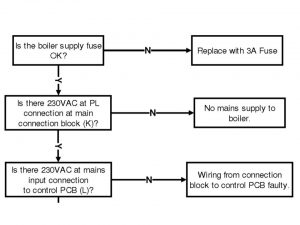
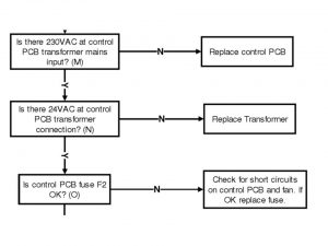
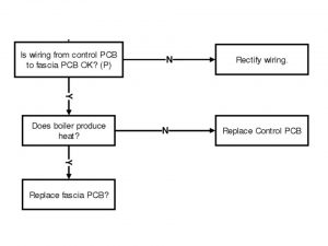
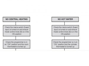
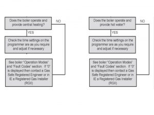
Fault finding chart for Keston C25 boiler
Fault finding table for Keston Combi boilers
| MAINS | BOILER | LOCKOUT | FAULT |
| off | off | off | No power to boiler. Check power supply |
| flashing | off | off | Boiler off on front. Turn User Control Knob to On. |
| flashing | off | off | External controls not calling for heat. |
| on | off | flashing | Flow Overheat. Reset boiler off then on via User Control Knob. Check circulation through system. Check by-pass fitted |
| on | off | flashing | Cabinet overheat. Replace thermal fuse link (82OC). Check for heat leak from gaskets. Check pump and fan run-on working OK when controls shut blr down. |
| on | off | flashing | Flue Overheat. Reset on stat. Fire boiler and check for actual flue temperature. |
| on | off | flashing | Should not occur. This is a spare sensor connection. This fault display indicates a fault on the wiring loom. |
| on | off | flashing | Ignition failure. The boiler has tried five times to fire and has not suceeded. Possible spark gap, gas pressure, flue/air blockage, condensate trap blocked, faulty ignitor or faulty ignition pcb. |
| on | off | flashing | Boiler lost flame whilst running. Check condense trap for blockage, flue/air blockage or bad combustion.. |
| on | off | flashing | Flow thermistor not connected or faulty. |
| on | off | flashing | Return thermistor not connected or faulty. |
| on | off | flashing | Water pressure low. Top up system pressure (if sealed system). Check boiler for leaks. Advise customer.. |
| on | off | flashing | Fan speed failure. The fan speed has dropped below 500 rpm. Check fan, connections and fan pcb. |
| on | off | flashing | Fan pcb faulty. – Replace |
The Keston boiler models C55P, C45 and C40P are unique in concept and design. Those boilers have a heat exchanger from stainless steel, lowest in class NOx emission (class 5), thanks to both boilres are designto provide super efficiency at condensing mode, giving smallest possible cabinet than can be safely hang on the wall. Boilers have a function of automaticly adjusting gas and air usage to demanded output of 12.6kW to 44.9kW (C45 & C40P) and 14.3kW to 55.2kW (C55P and C55). The integral Grundfos pump is automatically controlled to best match water flow rate to heat output & further increase appliance efficiency. To compromise underfloor heating Keston boiler models C55P, C45 and C40P are being supplied with separate inputs for central heating and hot water, signals are able to provide different temperatures at the same time for those two inputs . While the application for which the C55P, C45 and C40P were designed is the same as those which other boilers are used, Keston boiler models C55P, C45 and C40P have the added advantage of very high efficiency, and small which can be extended up to 45 metres horizontally or vertically.
Fault finding for Keston SPA water heating models
You shouldn’t switch off main water supply when you observe hot water release at tundish , the only thing that needs to be turned off is the power to electric elements. For indirect models you will need to turn off boiler heating option too. The cause of this could be a failure your installer or our service operator.
| SYMPTOMS | FAULT | ACTION |
|
no or low flow
|
poor mains pressure | check that all arrows on valves are in water flow direction. |
| restricted pipework | use larger diameter pipework | |
| mains stopcock | operate stopcock or replace | |
| sticking jumper in stop | replace stop cock | |
| blocked filter | clean filter | |
|
discharging cold
|
loss of expansion vessel | while hot tap open, verify and recharge vessel |
| defective pressure | pressure and reducing valve need to be exchanged | |
| blocked or defective | expand valve to relieve value mechanism to clear or replace | |
| crossflow from cold supply | check mixer taps and fit check through mixer top or other valve on hot outlet from heater fittings | |
|
water is cold
|
boiler not switched on (indirect) |
carry out procedure below
|
| air locked primary flow | ||
| thermostat settings incorect | ||
| cut out switch need reset |
Warning!!! (Electric Models). Always isolate the electrical supply before opening heating elements.Confirm that power supply is reaching the elements. If thermal cut off switches have operated press in the red button. If this fails to heat the cylinder the element has failed and should be replaced. Fit new element and reset thermal cut out output. If this is incorrect please replace the cut-out switch.
Keston System boilers (30) fault finding chart
Keston System boilers error codes
| CODE | DESCRIPTION | ACTION |
| F0 | Boiler Chip Card (BCC) Not Fitted | Please contact Keston (for boilers still under warranty) or alternatively a Gas Saferegistered Engineer for boilers outside warranty. |
| F6 | Outside Sensor Failure | Boiler needs resetting- follow resetting instructions. In instances where resetting doesn’t solve the issue contact Keston national service team (for boilers still under warranty) or an engineer that is Gas Safe Registered (for boiler outside warranty) |
| F7 | Low Mains Voltage | Contact a qualified electrician or your electricity provider. |
| F9 | PCB Fault | PCB Fault. Please contact Keston (for boilers still under warranty) or an engineer that is Gas Safe Registered for boiler outside warranty |
| L5 | 5 Boiler Resets in 15 minutes | 1. Turn power off and on at the fused spur.2. In instances when the boiler still doesn’t work properly please contact Keston (for boilers still under warranty) or an engineer that is Gas Safe Registered for boiler outside warranty |
| L6 | False Flame Lockout | Boiler needs resetting- follow resetting instructions. In instances where resetting doesn’t solve the issue contact Keston national service team for boilers still under warranty) or Gas Safe Registered Engineer for boiler outside warranty |
| C0 | BCC Start Fault | Boiler needs resetting- follow resetting instructions. In instances where resetting doesn’t solve the issue contact Keston national service team (for boilers still under warranty) or an engineer that is Gas Safe Registered for boiler outside warranty |
| C2 | BCC Fault | Boiler needs resetting- follow resetting instructions. In instances where resetting doesn’t solve the issue contact Keston (for boilers still under warranty) or an engineer that is Gas Safe Registered. |
| F1 | Low Water Pressure | Check system pressure is between 1 & 1.5bar on the pressure gauge. In instances when the boiler still doesn’t work properly then please contact Keston (if under warranty) or an engineer that is Gas Safe Registered. |
| L1 | Overheat of Temperature Flow | Verify if pressure on the gauge in the system is between 1 & 1.5bar When In instances when the boiler still doesn’t work properly then please contact Keston (if under warranty) or an engineer that is Gas Safe Registered. |
| F2 | Flame Loss | 1. Check other gas appliances in the house are working to confirm a supply is present in the property. |
| L2 | Flame Loss | 2. If other appliances do not work or there are no other appliances, check the gas supply is on at the meter and/or pre payment meter has credit. In instances when the boiler still doesn’t work properly then please contact Keston (for boilers still under warranty) or alternatively an engineer that is Gas Safe Registered. |
| F3 | Fan Fault | Boiler needs resetting- follow resetting instructions. In instances where resetting doesn’t solve the issue contact Keston national service team (for boilers still under warranty) or alternatively an engineer that is Gas Safe Registered. |
| F4 | Control / No Flow Thermistor | Boiler needs resetting- follow resetting instructions. In instances where resetting doesn’t solve the issue contact Keston national service team (for boilers still under warranty) or alternatively an engineer that is Gas Safe Registered. |
| F5 | Return Thermistor | Boiler needs resetting- follow resetting instructions. In instances where resetting doesn’t solve the issue contact Keston national service team for boilers still under warranty) or alternatively an engineer that is Gas Safe Registered. |
Keston System boilers reset procedure
To reset boiler, turn the B control mode knob to reset level, once done immediately turn the control knob B back to ON. After this boiler will try to ignite. If however fails you will need to the boiler still fails to light contact Keston national service team (for boilers still under warranty) or alternatively an engineer that is Gas Safe Registered.
Keston Qudos 28h boiler has an unique feature of error history. This internal memory function stores the last six errors encountered along with the sensor readings at that time and the time elapsed between each error occurring. This is very useful for diagnosing the cause of an error lockout, particularly when the error is intermittent. To activate it you need to press the “^” button repeatedly until the display shows “SHE” (“Show Errors”) and thenpress the “ENTER” button, you will enter the Error History mode. Press the “^” button to show the error number to investigate (Er1 is the most recent and Er6 is the oldest). Having selected the error press “ENTER”. Press the “^” to scroll through the readings stored at the time of the lockout occurring.
Keston Qudos 28h error codes
| SEQ. NO. | MEANING |
| Enn | The error code recorded for the lockout |
| 2 | Actual CH flow temperature (maximum 84C) – display indicates a radiator symbol and a “1” |
| 3 | Actual CH return temperature (maximum 72C) – display indicates a radiator symbol and a “2”. (NB Flow temperatures more than 20C above return temperature may lead to overheat and noise problems. Check the system pump performance and the system for blockages) |
| 4 | Actual DHW temperature – display indicates a tap symbol (NB Only relevant if the DHW sensor option is connected) |
| 5 | Actual Flue Temperature – display indicates the flame and fan symbols (NB: Flue temperatures above 75C may cause reduced boiler output. Flue temperatures above 80C will cause boiler lockout) |
| 6 | System water pressure, in bar. (Minimum 0.2 bar. The boiler will shut down if the water pressure drops below 0. bar) |
| 7 | Outside temperature – display indicates a small graph on the bottom row. (NB: Only relevant if an outside temperature sensor is detected) |
| 8 | Position in sequence: 0 – Initialise; 1 – Standby; 4 – Purge; 6 – Safety; 7 – Run; 8 – Postpurge; 9- Inter-Purge; 12 – Lockout |
| 9 | Time in hours since last error occurred |
Gas supply for all types of Keston boilers
A gas meter should be connected to the service pipe by the local gas region or their contractor. Before Keston boiler installation we advice that current meter should be checked to assure no failures to installation by meter faults or inability to provide demanded gas pressure.
Minimum/Maximum required Gas Pressure:
- natural gas pressure before the gas valve must be maintained at between 18 mbar (7.2 in WG) and 22 mbar (8.8 in) while the boiler is running.
- LPG pressure must be maintained between 31.5 mbar (12.4 in w.g) and 37.6 mbar (14.8in w.g) while the boiler is running.
Gas pressures above or below these levels will cause internal pressure issues with the gas valve. Minimal size for inlet supply pipes is 15mm. Before installing Keston boiler, you need to first think of diving gas source to other gas appliance at your real estate. Take into cosideration fact that if gas supply for a Keston boiler isn’t able to provide constant level of LPG between 31.5 mbar (12.4 in w.g) and 37.6 mbar (14.8in w.g) boiler will permanently fail to ignite. Pipe providing gas supply should be sized according to distance between meter and boiler. Further distance it is pipe size should be greater.
Repair and replacement parts
All Keston boiler repair and replacement parts are being supplied by national service boiler engineering team. All parts are being sourced by same manufactures used for original assets production. This way it guarantees quality, reliability and safety. There is one year guarantee for all ordered parts.
Safety First!
Initial steps
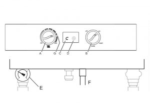
- Before starting to work on Keston boilers turn off the thermostat knob to O (Off) on the control panel cover
- When removing and replacing any parts that involve draining the system, close the boiler isolation valves and then drain the boiler using the presure gauge connection. It is forbiden to use the safety valve to drain the boiler.
- Always allow the boiler to cool and isolate the electricity supply.
- Always turn off the gas at the gas service cock.
- When removing any items containing water (hoses, pipes etc) make sure they do not spill on electrical components.
- Always replace consumable parts like o-rings and gaskets with new parts
- Always conduct electrical check such as polarity, continuity and resistance to earth with a multimeter before and after any work
Warning! Always test for gas soundness after completing any exchange of gas carrying components and carry out functional checks of controls.
Replacement of any component requires the removal of the outer case front panel. To remove it you need to remove the screws to the top and bottom of the cabinet.
Boiler Flow and Return Thermistors replacement
1) Isolate the appliance
2) Gain General Access -remove outer case front panel
3) Remove the push on connectors from the thermistor taking note of the correct positions.
4) Unclip the thermistor from the pipe.
5) Re-assemble in reverse order
Warning! When fitting the new thermistor it is an advantage to smear a thin film of heat sink compound between the thermistor and pipe. This, combined with fitting the new thermistor tightly to the pipe, ensures a good contact.
Cabinet Temperature Sensor replacement
1) Isolate the appliance
2) Gain General Access -remove outer case front panel
3) Remove the cabinet temperature sensor from the connector block by slackening the retaining screws
4) Re-assemble in reverse order
Flue Protection Thermostat replacement
1) Isolate the appliance
2) Gain General Access -remove outer case front panel
3) Remove the push on connectors from the thermostat taking note of the correct positions
4) Unscrew the two retaining screws, or nuts, and remove the thermostat
5) Re-assemble in reverse order
Warning! When fitting the new thermostat it is an advantage to smear a thin film of heat sink compound between the thermostat and plate. This combined with fitting the new thermostat tightly to the plate, ensures a good contact.
Water Pressure Switch replacement
1) Isolate the appliance
2) Shut off the water supply to the appliance
3) Gain General Access -remove outer case front panel
4) Drain the system to below the level of the appliance using the drain off tap at the base of the return pipe from the heat exchanger
5) Remove the push on connectors from the water pressure switch taking note of the correct positions
6) Unscrew the pressure switch
7) Re-assemble in reverse order
8) Refill the system
Main Control Box replacement
1) Isolate the appliance
2) Gain General Access -remove outer case front panel
3) Pull off the multi-pin connectors and HT lead away from the board
4) Remove the three retaining screws securing the control block to the boiler backframe
5) Remove the control
6) Re-assemble in reverse order
Combustion Blower replacement
1) Isolate the appliance
2) Gain General Access -remove outer case front panel
3) Disconnect the two connector blocks from the combustion blower
4) Unscrew the bolts securing the venturi to the inlet port tap at the base of the return pipe from the heat exchanger Note of the correct positions.
5) Remove the four bolts securing the combustion blower outlet flange to the burner and remove the combustion blower.
6) Re-assemble in reverse order
Warning! When reassembling inspect any gaskets for damage and replace if necessary.
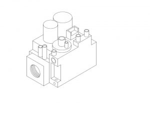
Gas Control Valve replacement
1) Isolate the appliance
2) Gain General Access -remove outer case front panel
3) Remove the push on connector block to the gas valve.
4) Undo the union fitting securing the gas inlet pipe to the gas control valve.
5) Undo the four bolts fixing the mixing venturi to the gas valve.
6) Remove the gas valve.
7) Unscrewing the union fitting from the gas valve.
8) Re-assemble in reverse order
9) Check the gas rate and combustion
Gas Injector – C40P and C55P boilers only
1.) Isolate the appliance
2) Gain General Access -remove outer case front panel
3) Undo the four bolts fixing the mixing venturi to the the gas control valve
4) Remove the injector from the outlet port of the gas valve
5) Insert the new injector
6) Re-assemble in reverse order
7) Check the gas rate and combustion
Spark Ignition/Flame Detection Electrode replacement
1) Isolate the appliance
2) Gain General Access -remove outer case front panel
3) Remove the pull off HT lead to the spark ignition electrode.
4) Undo the screws to the spark ignition electrode flange located on the heat exchanger side panel and withdraw the spark ignition electrode
5) Re-assemble in reverse order
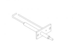
Warning! When reassembling inspect the gasket for damage and replace if necessary. With the new spark ignition electrode in place it is essential to ensure the gap between the tip of the electrode and the earth post is 3 mm. Distances above or below 3 mm will affect ignition performance. If necessary gently bend the electrode taking care not to damage the ceramic insulator.
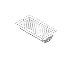
Burner replacement
1) Isolate the appliance
2) Gain General Access -remove outer case front panel
3) Remove the combustion blower
4) Remove the 12 nuts fixing the burner to the top of the heat exchanger.
5) Withdraw the burner from the top of the heat exchanger.
6) Re-assemble in reverse order
Warning! When reassembling inspect any gaskets for damage and replace if necessary.
Heat Exchanger replacement
1) Isolate the appliance
2) Gain General Access -remove outer case front panel
3) Shut of the water supply to the appliance.
4) Remove the burner
5) Drain the system to below the level of the appliance at the base of the boiler return pipe.
6) Remove the flue protection thermostat
7) Remove the spark ignition/flame detection electrode
8) Remove the flue connection by slackening the retaining strap and pulling the flue off the heat exchanger spigot.
9) Remove the condensate trap hose by releasing the retaining clamp and pulling the hose away from the spigot at the base of the heat exchanger flue outlet box.
10) Disconnect the flow and return pipe unions from the heat exchanger.
11) Remove the two screws fixing the heat exchanger to the top mounting bracket
12) Remove the heat exchanger
13) Re-assemble in reverse order
14) Recommission
Condensate Trap replacement
1) Isolate the appliance
2) Gain General Access -remove outer case front panel
3) Disconnect the condensate line from the base of the heat exchanger.
4) Disconnect the condense line from the projection of the condensate trap from the base of the cabinet.
5) Withdraw the condensate trap.
6) Mop up any spilled condensate.
7) Re-assemble in reverse order
Warning! When re-fitting the condensate trap pour water onto the condensate hose from the base of the heat exchanger until nearly full. Then reconnect the condensate hose to the base of the heat exchanger.
Pump replacement
1) Isolate the appliance
2) Gain General Access -remove outer case front panel
3) Isolate the waterways to the pump using the pump isolation valves
4) Disconnect the pump electrical cable from the connections box of the pump head taking note of the correct position
5) Remove the four allen bolts securing the pump head to the pump back plate.
6) Remove the pump head.
7) Re-assemble in reverse order
Condensate Trap replacement
1) Isolate the appliance
2) Gain General Access -remove outer case front panel
3) Disconnect the condensate line from the base of the heat exchanger.
4) Disconnect the condense lines from the projection of the condensate trap from the base of the cabinet.
5) Withdraw the condensate trap.
6) Mop up any spilled condensate.
7) Re-assemble in reverse order
Warning! When re-fitting the condensate trap pour water onto the condensate hose from the base of the heat exchanger until nearly condensate hose to the base of the heat exchanger.
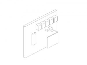
Control PCB replacement
1) Isolate the appliance
2) Gain General Access -remove outer case front panel
3) Remove the fascia plate by removing the four retaining screws and pull forward leaving to one side
4) Remove the right hand side panel to the control boards housing by sliding toward
5) Pull off the multi-pin connectors away from the board
6) Slide the control PCB from the PCB housing.
7) Re-assemble in reverse order
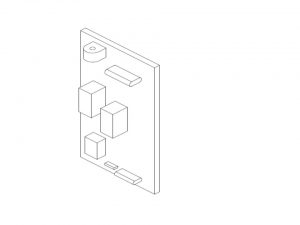
Fascia PCB replacement
1) Isolate the appliance
2) Gain General Access -remove outer case front panel
3) Remove the user control knob by fulling forward off the shaft.
4) Undo and remove the locknut securing the fascia PCB to the front plate of the controls housing.
5) Disconnect the fascia PCB by unplugging the 13-way connection block.
6) Re-assemble in reverse order
7) Check for correct operation of the fascia PCB.
To ensure the continued safe and efficient operation of the boiler it is necessary to carry out routine servicing at regular intervals. This how often servicing needs to happen depends from particular boiler operating conditions, but it is recommended that an annual service should be carried out by a Keston national service engineer.
Warning! When servicing ensure that the gas and electrical supplies to the boiler are isolated before any work starts. It should be noted that setting the user controls to “Standby” does not isolate the electrical supply and parts of the boiler will remain live. Hazardous materials are not used in the construction of the C45, C40P and C55(P). However, due care should be taken when handling boiler components. All joints should be checked for soundness after servicing and before firing the appliance.